

The BJTs and MOSFETs are two of many commonly used components that you will come across when working with electronics. BJTs are three-terminal devices that are used for switching or amplification of a signal. A MOSFET on the other hand is a four-terminal device that is mainly used for switching applications. This article is made to clearly put the difference between BJTs and MOSFETs on the table with a practical approach in mind.
What is the Difference Between a BJT Transistor and a MOSFET Transistor?
Before going any further into the article let’s clear out the basics about MOSFET and BJT. If you already know the basics you can skip this part.
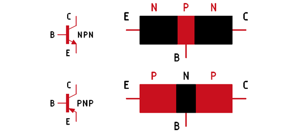
A BJT stands for Bipolar Junction Transistor. These are small three-terminal devices namely (Emitter, Base, and Collector) that can be used as a switch or an amplifier.
There are mainly two types of transistors NPN and PNP. An NPN transistor is constructed by placing a P-type semiconductor sandwiched in between two N-type semiconductor materials. And the opposite is true for the PNP transistor. In the above image, we have shown both the symbol and construction of these two different types of transistors.
BJTs are current-controlled devices, which that means to control the flow of current between the emitter and collector, current should first flow in between the base and emitter junction. So with a very small base current, you can control a huge amount of collector current. The ratio of the transistor’s collector current (Ic) to its base current (Ib) is known as the beta(β) value. BJTs are commonly used in a wide range of applications including audio amplifiers, power supplies, and digital logic circuits.
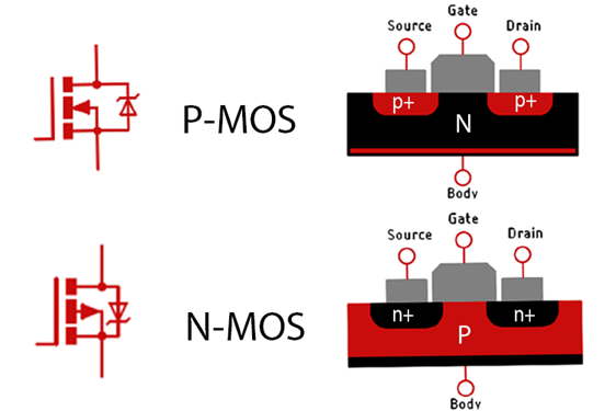
MOSFET stands for Metal Oxide Semiconductor Field Effect Transistor. Similar to BJTs, MOSFETs are made of three different layers of material. A metal layer, a semiconductor layer and an oxide layer, and it also has three terminals: the Gate, Drain and Source. But often you will hear that MOSFET is a four-terminal device and that’s also true because the fourth terminal is called body terminal and for generic MOSFETs, it is internally shorted with the Drain terminal.
BJTs and MOSFETs are both Transistors, and both of those can be used to switch or amplify a signal. But due to the internal construction, a MOSFET provides certain advantages over BJTs when it comes to switching applications.
Unlike BJTs, MOSFETS are voltage-controlled devices. That means to turn on a MOSFET you need to provide a certain level of voltage to its gate terminal. So, with very little voltage in the gate, you can control a very huge drain current. You can check out the VGS VS ID curve of a MOSFET to get more information on the topic. We can classify N-MOSFETs and P-MOSFETs into two subcategories, enhancement mode, and depletion mode. Enhance Mode MOSFETs will turn on when there is a positive voltage present in the gate(G) terminal. The depletion mode. MOSFETs will turn on when the gate of the MOSFET is connected to the ground pin.
| Parameter | BJT | MOSFET |
|---|---|---|
| Full Form | BJT stands for Bipolar Junction Transistor. | MOSFET stands for Metal Oxide Semiconductor Field Effect Transistor. |
| Type | BJTs are divided into two types: NPN and PNP. | MOSFETs are also divided into two types P-Channel and N-Channel and both have enhancement and depletion versions. |
| Structure | BJT is a currently controlled device. | Consists of an emitter, base, and collector |
| Operation | Amplification and switching | Amplification, switching, and voltage regulation |
| Power consumption | BJT consumes more power than MOSFET. Due to Internal Losses | The power consumed by a MOSFET is less than BJT. because a MOSFET has a very low Turn on Resistance defined by RDSon, and it’s in the milli ohms range. |
| Polarity | BJT is a bipolar device. | MOSFET is a unipolar device. |
| Noise immunity | Lower noise immunity | Higher noise immunity |
| Input impedance | BJT has low input impedance. | MOSFET is a voltage-controlled device. |
| Switching speed | BJT has a lower switching speed compared to MOSFET. | For MOSFET, the switching speed is relatively high. |
| Input Control | MOSFET has a very high input impedance. | In MOSFET, both electrons or holes can act as charge carriers depending on the type of channel between the source and drain. |
| Voltage | BJTs come with Lower Voltage Ratings. | MOSFETs come in Higher Voltage Ratings. |
| Current | Lower current handling capability | High Current Handling Capacity |
| Charge Carriers | In BJT, both electrons and holes act as charge carriers. | In MOSFET, both electrons or holes can act as charge carriers depending on the type of channel between source and drain. |
| Cost | Lower Manufacturing Cost | Higher Manufacturing Cost |
Difference Between BJT and MOSFET
The following table summarizes some of the major differences between BJTs and MOSFETs.
Using BJTs and MOSFETs in Practical Applications
BJTs and MOSFETS serve a crucial role in any modern-day application, and In this section of the article, we will try to understand the working of those with some practical examples. At the end of the article, the reader will have a clear idea about BJTs and MOSFETs and how they affect modern-day electronics.
Applications of BJT as a Switch
There are many applications for BJTs as switches. In this part of the article, we will try to provide some practical applications of BJTs as a switch.
Configuring a BJT as a switch is the most common application, and in the above image, we have configured an NPN and PNP transistor as a switch. In this configuration when the transistor is in on condition current flows through the load and when it’s in off state no current flows through the transistor.
In the circuit the NPN transistor is turned on by applying a positive voltage to the base. And the PNP transistor is turned on by applying a negative voltage to the base of the circuit.
Relay Driver: the most common switching application for a BJT is a relay driver. A BJT can be set up to control the switching of a relay, now the relay can be used to turn on a bigger load like a light bulb or motor.
LED Driver: The BJT can also be configured as a LED driver. Not only can it be used to drive high-power LEDs, but with a PWM signal the brightness of the LED can also be adjusted. Motor driver: The BJT can be used to control the RPM of the motor by varying the total amount of power supplied to it. This can be done using a PWM signal or a specially designed motor driver circuit.
Primary Switch in SMPS: BJTs can also be used as a primary switcher for a power supply. Power supplies in the range of 10 to 25 watts use a self-oscillating driver circuit which consists of a BJT.
High Power LED Driver Circuit with BJT:
The next example in our list is this high-power LED driver circuit. Let’s take an example of a 12V 5A LED, and for your application, you want to use an ESP8266/ESP32 to drive it. So what part will you choose, a BJT or a MOSFET? Which will be the most cost-sensitive for your design.
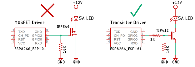
In the above circuit the transistor driver is made of a TIP41C transistor and the MOSFET driver is made of IRF540 MOSFET both are two pretty common part numbers. But the MOSFET driver circuit is incorrect and the circuit will not work as a LED driver because the IRF540 MOSFET has a gate threshold voltage of 4V and if you are driving the MOSFET with a 3.3V logic the MOSFET won’t even turn on thus your LED will also be in an off state.
The solution is to use a logic level MOSFET but that also comes with an additional cost. So, for a 5A load driver circuit like this, a transistor would be a far better choice than a MOSFET in terms of cost and circuit complexity. But if your application demands high-speed switching then or other critical parameters you should definitely go for a MOSFET.
Single Stage Class-A Amplifier Circuit:

The simplest form of amplifier is a class A amplifier circuit. This type of circuit uses a single transistor for its output stage with a load resistor directly connected to the collector of the translator. When the transistor is on it sinks current through the load resistor resulting in an inverted voltage drop across the resistor.
The efficiency of this type of circuit is very low (about 30%), so it delivers a very small output power and drains high DC power. Because of this poor efficiency, a large heat sink is needed to cool the transistor.
So why should we use a class A amplifier instead of other alternatives? Because a class A amplifier provides high linearity and low distortion making it suitable for high-fidelity audio applications.
To improve the efficiency of the class A amplifier circuit, the Darlington Transistor configuration was introduced, in this configuration the circuit replaces the single transistor with two transistors thus improving the overall efficiency of the circuit.
A very practical example of a translator amplifier is the 100 Watt amplifier circuit that is shown in the schematic below, the circuit uses a Darlington pair configuration for the preamp stage to drive the power stage.
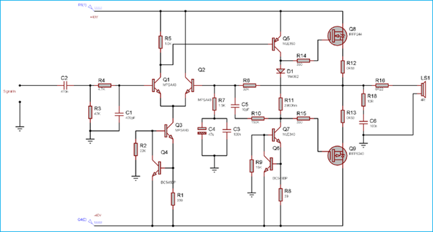
The schematic shown above is a very popular 100W MOSFET Amplifier Circuit which you can find more details on circuitdigest.com but as you can see in the schematic after the RC Input filter the Q1 and Q2 is configured as a differential amplifier and the Q3 and Q4 transistor is a Darlington pair amplifier.
Most Common Application of MOSFETs with Example:
In the above example, we have told you why a transistor can be a better choice for some applications. Now in this section we will discuss some applications of MOSFETs.
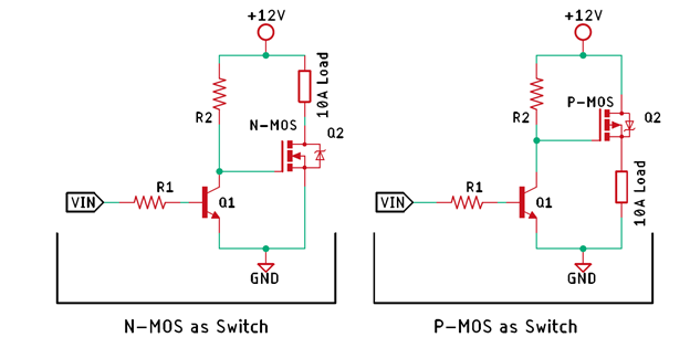
There is no doubt that for high power loads, MOSFET is a better driver than a BJT. it has High input impedance, Low on-state resistance, High switching speed, and on top of that all that it requires very little current in its gate terminal to turn on. But there are some disadvantages of mosfet also.
Take an example of the two MOSFET driver circuits shown above. They are generic N-MOS and P-MOS, let’s assume they are IRF540(N-MOS) and IRF9540(P-MOS) respectively. If you want to drive it with 3.3V logic level microcontrollers or is because of the high gate threshold voltage, those won’t even turn on. The solution is to use a logic level MOSFET but will just increase the BOM cost. A cheaper alternative will be to use a transistor driver paired with the final MOSFET driver, not only will this configuration properly drive the MOSFET it will significantly reduce the BOM cost. Though one disadvantage of this circuit is that the logic to turn on the circuit will be inverted.
Application of MOSFET in an SMPS circuit:

For the Next example we will be looking at a simple block diagram of an SMPS circuit where a MOSFET is used as a primary switcher element, A MOSFET has a fast-switching speed, low on-resistance, and the ability to handle high voltage and currents. In an SMPS circuit, a MOSFET is used to switch the high-voltage DC, to create a high-frequency AC signal. and because of this high-frequency AC signal, it’s possible to reduce the transformer size and make a more compact and efficient power supply.
In an SMPS circuit MOSFETS are preferred over BJTs due to their low power dissipation and higher efficiency, the efficiency can also be increased by using a proper gate driver circuit Which further simplifies the operation and reduces cost and complexity.
In many high-power applications like EV chargers, High Power SMPS (2.5KV -55KV), a MOSFET is used as the replacement for the output diode, this type of converter is called a Synchronous Rectifier. Synchronous rectification using MOSFETs can significantly reduce power loss and improve efficiency in SMPS circuits.
In conclusion, MOSFETs and BJTs are electronic components used in a variety of applications. While both are used for amplification and switching, the overall choice between using a MOSFET or a transistor in an application depends on the specific requirements of the application. If high impedance and low on-resistance are important factors, then a MOSFET may be the best choice, on the other hand if stability and reliability is a concern a BJT will be a better choice.

2 thoughts on “Understanding the Differences BJT and MOSFET with Practical Examples”
Hey! Someone in my Facebook group shared this site with us so I came to take a look.
I’m definitely loving the information. I’m book-marking and will be tweeting this to my followers!
Superb blog and brilliant style and design.
Thank you for your kind words! Please share the post with others.